TALES FROM THE CRYPT
A LOOK BACK AT THE ORIGINS OF THE PXYL MICROSCOPE
The PXYL Microscope started as a way to demonstrate the laser that we had made. The laser was a Yb:YAG laser in the first instance, later to become a Yb:KGW source, which provided shorter laser pulses, better suited to multi-photon microscopy.Multi=photon microscopy relies on an ultrafast laser source (a laser that emits short pulses of the order of 100 femtoseconds). These type of lasers have typically been quite difficult to build for a number of reasons. The repetition rate of the laser is detremined by the optical cavity length. Light travels at a fixed speed and takes an amount of time to circuit the laser cavity. This sets the time between pulses -the cavity round trip time. Historically lasers have been built with repeition rates of about 100MHZ which means the cavity is about 1.5 metres long. The reason for that repetition rate is another historical legacy. Detectors are typically not able to detect pulses faster than 100MHz, so in order to detect the optical pulses the optical repetiton rate had to be less than what the electrical detectors could detect. The other reason to have a lower repetition rate (and hence longer cavity) is that the energy in each pulse is inversly proportional to the repetition rate. So if you have lots of pulses per second then each pulse has less energy. For most non-linear optical effects you need large pulse energies to see the non-linear effects. So again this favours the longer cavity. Also historically, multi-photon microscopes have required >1 W optical power from the laser. this is because the microscopes were not optimised for ultrashort laser pulses. They were inefficient meaning that more laser power was needed in order to acheive the 10-20mW needed at the sample. This means that you have to design a laser giving >1W with a cavity of >1.5m. The laser power leads to thermal effects and the cavity length means that the optical alignment becomes challenging. Combine the two requirements and you have a problem; particularly in a product if you want that product to be "hands off" operation. Historically these systems were not hands off and required an expert user to maintain and operate them. Not ideal for the biologist wanting to concentrate on the biology. To solve these problems I came up with a laser manufacturing technique that offered maximum stability by allowing a very compact design. The smaller the laser footprint the more stable it will be against perturbations. To make it compact I removed everything that was not necessary in the design. Most solid state lasers have optical adjustement in them because that adjustement is needed to keep them operating under all conditions. If you make it inherently stable then you do not need the adjustment and can therefore have a very compact design. I ended up with a "glass on glass" archetecture were the glass mirrors are mounted directly onto a glass substrate. Everything (more or less) was glass, so stresses from thermal expansion were minimised producing a very stable arrangement. The second part of the problem, the thermal one, wa solved by addressing the microscope. By making it more efficient, by which I mean taking transmission from 10% to 99% I reduced the power requirement. Then the laser could be lower power and produce less heat. It is all win - win.
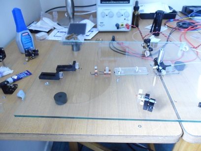
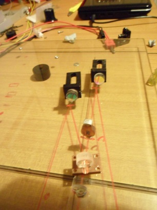
The first attempt was on a glass door of an old hi-fi cabinate. The optics were glued onto metal sub-mounts. But many of those proved unnecessary and were removed in further optimisation.
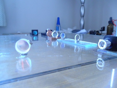
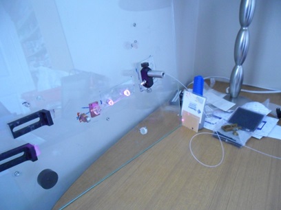
The laser even worked on its side, which for such a crude experiment was remarkable.
On of the nice extras of this technique was that you could draw the laser resonator and mirror positions on with a ruler and pen, or print out the cavity from optical cavity design software and stick the picture to the underside of the glass. You can then just place the optics in the correct place. Redesign was very easy.
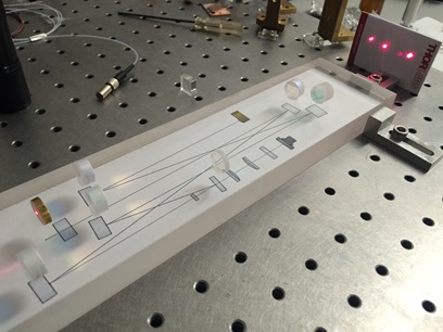
The concept was refined by getting a thicker piece of glass cut to the correct size. Removing unnecessary metal sub-mounts by using tooling and alignment jigs, and creating an optical cavity that was over 1 m in length in a tiny form factor.
On a limited budget it was difficult to make a laser scanning microscope because of the cost of the scanning components. So I set about trying to scan the laser beam in other ways - using what I had available in the garage and the loft. I had a few loud speakers and an old audio amplifer, so it occured to me to use them to make things move in a sinusoidal fashion. The first attempt was to attach mirrors to the loud speakers and get the mirrors to tilt when the speaker vibrated. This video shows the setup. The problem then was the distortions caused by the angles through the lens. In a conventional laser scanning microscope this is handled by scan and tube lenses, which are telescopes designed specifically for the purpose. The multi-element object lens is also designed to accomodate the incoming angles. All these components are expensive. So an alternative was sought.
The next adaptation, was realatively simple, attach a lens to the speaker cone directly and get the whole thing to vibrate. When I shone the laser through the lens I was pleased to see that the focus of the beam moved too -in perfect unison with the lens. It was then a case of trying to get the lens to move in 2 dimensions. Using business cards as flexures attached to two speakers it was possible to get the lens to move in 2 dimensions. This was then formalised using 3D printing to get our patented scanner. Video.
There were then various exotic implementations including the famous Meccano and Lego versions.
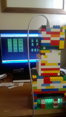
The Legoscope
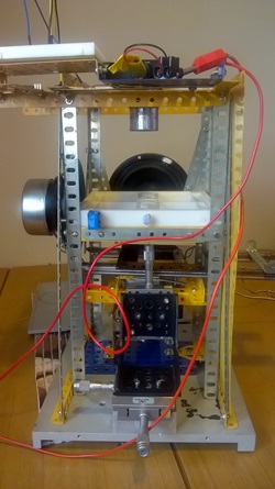
The Meccanoscope
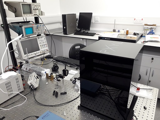
With a bit more funding available, we were able to make a fully functioning prototype system. It is very similar to the Meccanoscope internally, but a bit more sophistiscated. This video shows the first protype in action.